Steve Koci’s DIY RC Controller Addikit

New for 2020, it’s Steve Koci’s DIY RC Controller Addikit

Boffintronics partnered with Addicore and Steve Koci of DIY Animatronics to create this kit. Steve is a writer for Servo Magazine and has had his animatronic articles published in the book The Ultimate Guide To DIY Animatronics. The DIY RC Controller Addikit is featured in an article written by Steve in a recent issue of Servo Magazine.

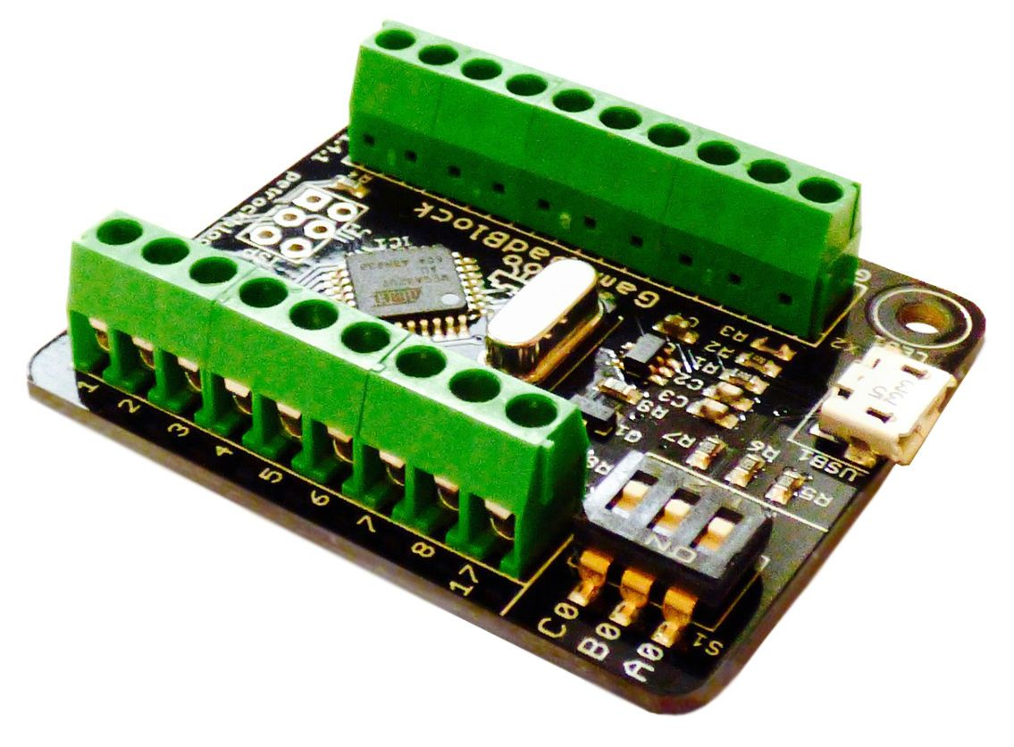
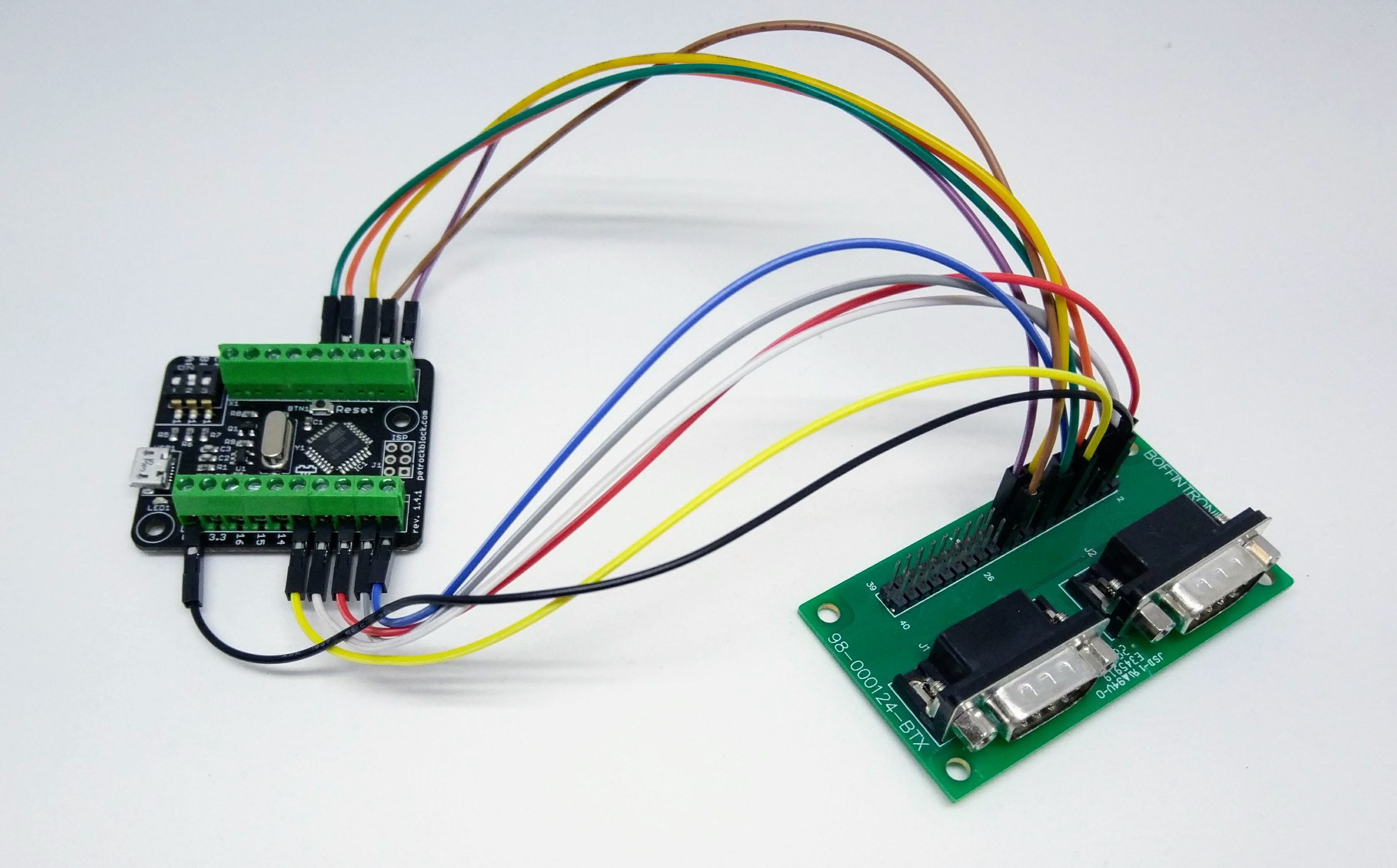
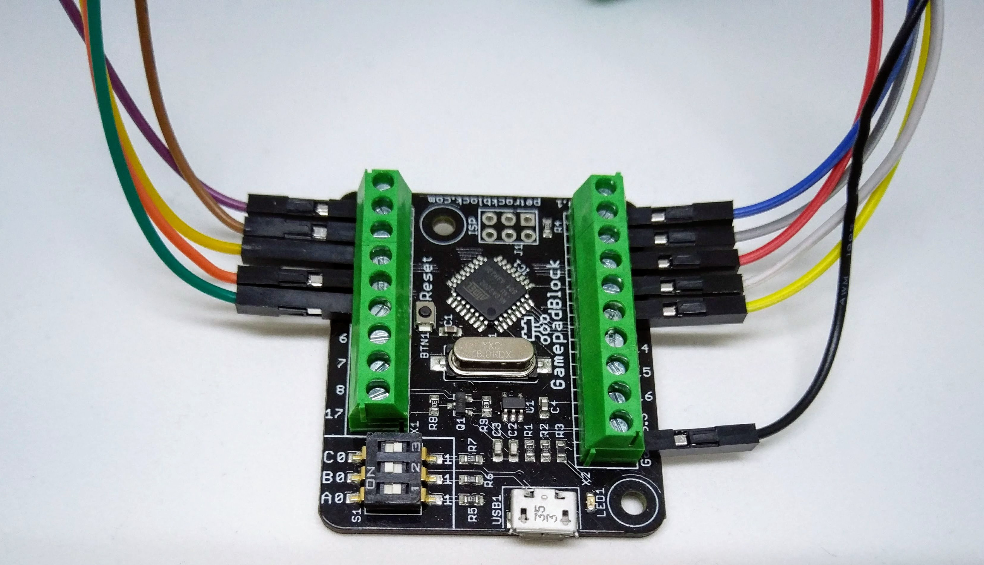
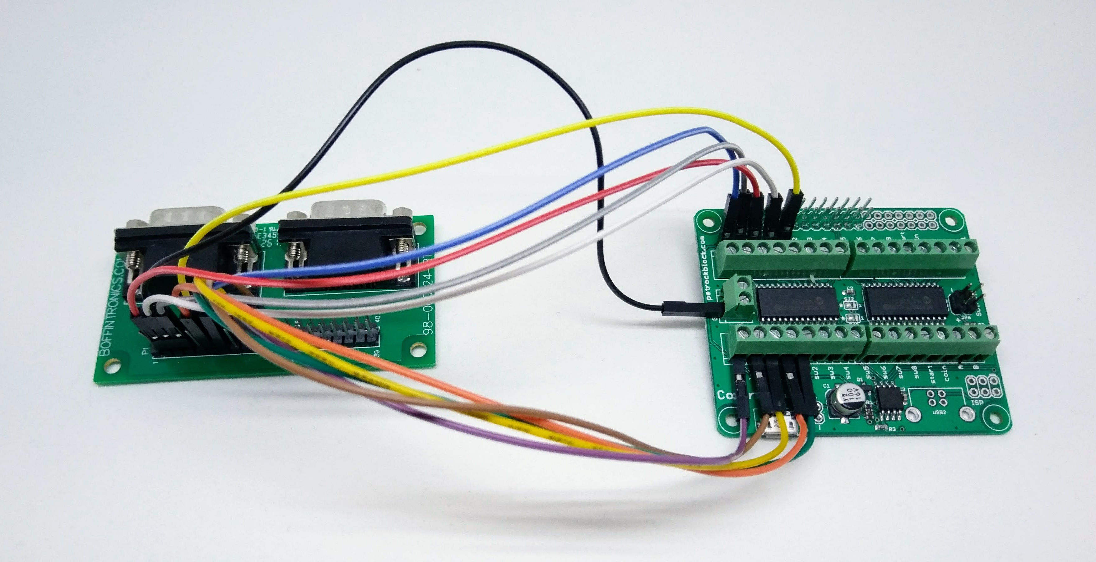
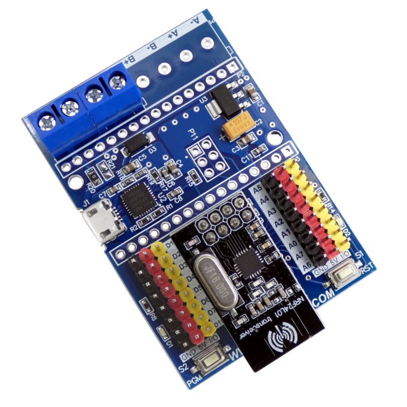
The DIY RC Controller Addikit is a general purpose RC controller and receiver based off of the ATmega328P and the nRF24L01+ 2.4GHz Wireless Transceiver. With 2 XY joysticks, 2 slide pots, 6 buttons, and 2 toggle switches, the DIY RC Controller gives you many different ways to control animatronic displays, puppets, robotics, vehicles, drones, and much more!

Out of the box the included Arduino sketches allow for the control of 6 servos and 6 digital outputs. There is extra IO on board the receiver that can be utilized if you are willing to roll up your sleeves and tweak the code.

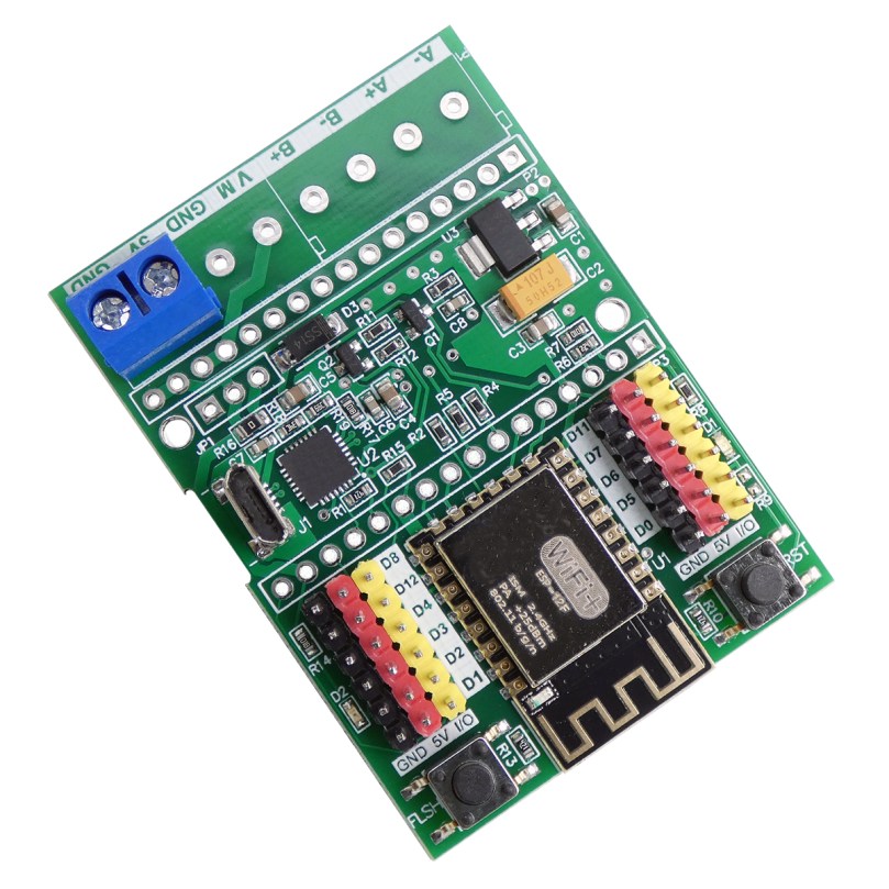
Want to control more than one receiver? The DIY RC Controller Addikit has the ability to control up to 4 receivers in multi-mode.

The Addikit comes with 1 FEETECH (Fitec) FS90 9G Mini Servo and 1 Boffintronics RC Receiver board to get you started. Additional servos or receiver boards are available.

The DIY RC Controller Addikit is powered by 4 AA batteries (not included) or you can upgrade your controller with a 2x 18650 lithium battery holder.

SETUP AND CONFIGURATION VIDEO:

SERVO SETUP VIDEO: 

Purchase at Addicore.com

Boffintronics RC Receiver

This is the custom designed Boffintronics RC Receiver board used in the Steve Koci’s DIY RC Controller Addikit. It is based on the ATmega328P and is compatible with the Arduino IDE as a Nano.

Included on the board is an 8 pin header for an nRF24L01+ 2.4GHz Wireless Transceiver.

The board includes an on-board USB Micro connector and USB to serial (UART) converter, making it easy to power and program the board by simply connecting it to your computer with a USB Micro cable.

There are 16 headers set up for driving servos (5V, signal, and ground). Additional signals provided via P2 and P3.

Purchase at Addicore.com

Cardboard Sumo Bot AddiKit

As seen at the San Diego Maker Faire, we developed this kit with Addicore and the San Diego Makers Guild as an easy way to build a cardboard bot that is controlled via a smartphone or tablet.

Wait, you’re telling me you don’t have any idea what a cardboard sumo bot is? The rules are simple, just use your bot to push another bot outside of a circle drawn on the ground. You can even add weapons, like a flipper, to the bot to gain an advantage. A video taken at the 2018 San Diego Maker Fair is embedded below. 

This AddiKit also makes a great robot platform for experimenting with servos and sensors and allows for expandability.

Addicore also offers this kit for education and events. Visit Addicore.com for more information.

BUILD INSTRUCTION VIDEO

SMARTPHONE / TABLET CONTROL VIDEO: 

IN ACTION! 

Purchase at Addicore.com

Boffintronics RoboBoffin Mini Controller

This is the custom designed Boffintronics RoboBoffin Mini control board used in the Cardboard Sumo Bot Addikit. It is based on the ESP8266 ESP-12F module and is compatible with the Arduino IDE and with NodeMCU.

The board includes an on-board USB Micro connector and USB to serial (UART) converter, making it easy to power and program the board by simply connecting it to your computer with a USB Micro cable.

Included are 12 headers set up for driving servos (5V, signal, and ground). Additional signals provided via P2 and P3.

Each board will come with the Cardboard Sumo Bot Driving software already installed. You can easily reprogram with your own code.

Purchase at Addicore.com

Boffintronics Solder Breadboards


Have you ever had wires or components fall out of your solderless breadboard just as you are preparing to show it off ? Or maybe just picked up an older project and wondered why it doesn’t work anymore? Or worse, where did all the parts go!? We have! And that’s why we created these awesome solder breadboards.

Solder breadboards, or perfboards as they are sometimes called, are a great way to ruggedize and replicate your favorite breadboard creations.

This board matches standard white and transparent 400 tie-point breadboards.

Designed with the same row and column layout as standard solderless plugin breadboards, transferring or copying a design couldn’t be easier.

The rows and columns are labeled just like the solderless breadboards for easy reference, the circuit pads are gold plated for superior solderability and the white soldermask makes your projects look awesome!

Now available for purchase at Addicore.com
Solder Breadboard 170
Solder Breadboard 170 with Power Rails
Solder Breadboard 400

Using the Boffintronics C64 / Atari Joystick Adapter with a Raspberry Pi

ad410_top

There have been a few questions about how to hook up the Boffintronics C64 / Atari Joystick Adapter to a Raspberry Pi. Here is a quickstart guide to get you up and running so you can enjoy all of that retro computing magic!

1. Plug in the Boffintronics C64/Atari adapter to the Raspberry Pi using the GPIO Ribbon Cable.

Make sure that Pin 1 on the Pi is connected to Pin 1 on the adapter board. The picture below has Pin 1 on the top of both boards.C64toPiwiring

2. Install Retrogame from Adafruit.

SSH into your Pi
Run the following at the prompt

curl https://raw.githubusercontent.com/adafruit/Raspberry-Pi-Installer-Scripts/master/retrogame.sh > retrogame.sh

Then run

sudo bash retrogame.sh

Select option 3

3. Replace /boot/retrogame.cfg with the retrogame.cfg file from here and reboot.

I have the joysticks mapped to the following keyboard keys

LEFTCTRLJ1 Button 1
UP J1 Up
DOWN J1 Down
LEFTJ1 Left
RIGHTJ1 Right
RIGHTCTRLJ2 Button 1
8J2 Up
2J2 Down
4J2 Left
6J2 Right

You can change the keyboard keys to anything that you want in the retrogame.cfg file, just don’t change the column of numbers that set up the GPIO. Those are mapped to the proper signal lines on the joystick ports on the adapter.

Boffintronics Haptic Feedback Module

Have you ever wanted to add haptic feedback to an existing project? Boffintronics has you covered! We’ve created a haptic feedback module that you can integrate quickly and easily.

The module consists of an ERM (eccentric rotating mass) style vibration motor and a MOSFET driver. It can be powered from 3.3V power pin and the enable (VB pin) can be driven from any 5V or 3.3V digital output pin.

The module has 0.1″ connectors on the bottom for plugging into standard breadboards as well as terminal blocks to connect wires.

Purchase one at Addicore.com

Boffintronics Audio and Video Breakout Boards

avbreakouts20180126
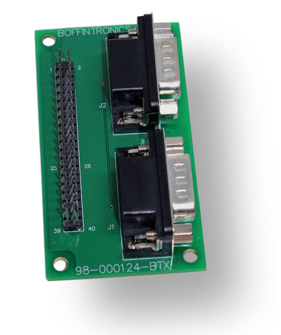
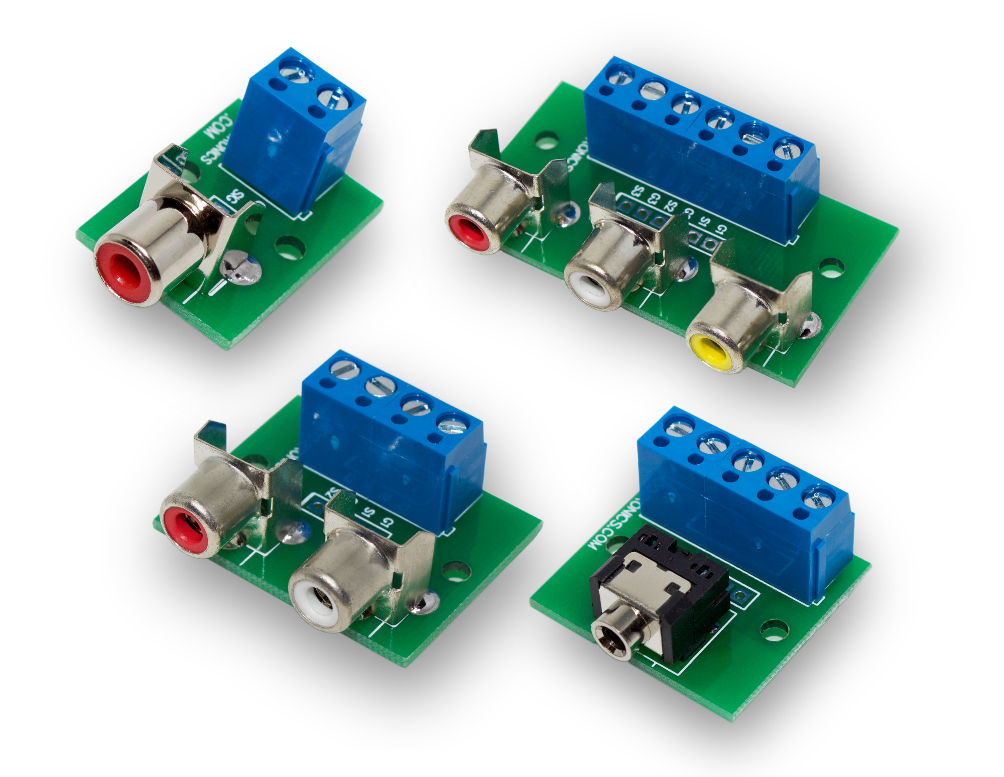
Boffintronics has created a line of audio and video breakout boards for RCA and headphone jacks.

ad207_bottom
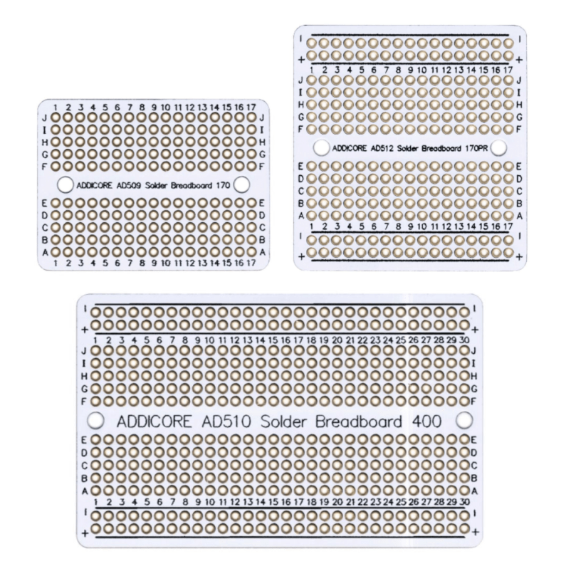
Each has 0.1″ connectors on the bottom for plugging into standard breadboards as well as terminal blocks to connect wires.

We have 4 different boards, all available at Addicore.com;

Single RCA with 5 different RCA jack color options

Dual RCA with red and white RCA jacks

Triple RCA with red, white, and yellow RCA jacks

3.5mm headphone jack with integrated switch


How to use the Boffintronics C64 Board with PetRockBlock’s GamepadBlock

PetRockBlock has also come up with the GamepadBlock. The GamepadBlock adds 17 inputs for additional joysticks or buttons. The GamepadBlock connects to a computer as a standard USB Human Interface Device (HID). Since HID is a standard protocol, the GamepadBlock can be used with Windows, Mac, Linux, and many other systems.

ad463_top

Addicore is the exclusive US distributor for all of PetRockBlock’s boards, including the GamepadBlock. Addicore also carries the Boffintronics C64 Board as well as hookup wires.

The GamepadBlock does not have separate inputs for Player 1 and Player 2 as the ControlBlock has, just numbered inputs 1-17. To make things simple, I hook up Player 1 on the left and Player 2 on the right.

gamepadblock_c64_20180123a

To hook them up, connect the following wires;

Joystick Input C64 Board GamepadBlock
Player 1 – Right Pin 21 Terminal 1
Player 1 – Left Pin 22 Terminal 2
Player 1 – Up Pin 19 Terminal 3
Player 1 – Down Pin 11 Terminal 4
Player 1 – Button Pin 16 Terminal 5
Player 2 – Right Pin 13 Terminal 9
Player 2 – Left Pin 7 Terminal 10
Player 2 – Up Pin 3 Terminal 11
Player 2 – Down Pin 5 Terminal 12
Player 2 – Button Pin 12 Terminal 13
Joystick Ground Pin 6 Terminal GND

For the GamepadBlock to work correctly with the C64 board, the firmware must be updated to at least version 1.2.0. The instructions to update the firmware is here.

Set the DIP switches to the correct mode for C64 and Atari controllers. (A=1, B=0, C=1). This mode allows for the best functionality in the C64 emulator VICE as well as MAME.

gamepadblock_c64_20180123b

Note: If you are using the GamepadBlock on a Linux based system, such as the Raspberry Pi, you will need to patch the OS to allow for 2 player functionality. The instructions for the patch is located here.

How to use the Boffintronics C64 Board with PetRockBlock’s Controlblock

While the Boffintronics Commodore 64 Adapter board can be hooked directly up to the GPIO of the Raspberry Pi, one of the easier ways is to use the PetRockBlock ControlBlock.

ad435

The ControlBlock is an add on board for the Raspberry Pi that adds 32 extra inputs for additional joysticks or buttons. The ControlBlock also allows for adding a power switch and LED with intelligent start up and shutdown scripts.

Addicore is the exclusive US distributor for all of PetRockBlock’s boards, including the ControlBlock. Addicore also carries the Boffintronics C64 Board as well as hookup wires.

Hooking up the C64 board is fairly simple since standard Commodore and Atari joysticks are just switch closures that ground the corresponding pin on the connector. Each joystick will require 5 connections plus a ground.

The ControlBlock breaks up the inputs so that Player 1 is on one side and Player 2 is on the other.

controlblock_c64_20180123

For Player 1, connect the following wires;

C64 Board ControlBlock (Player 1)
Pin 21 Right
Pin 22 Left
Pin 19 Up
Pin 11 Down
Pin 16 SW1
Pin 6 GND

For Player 2, connect the following wires;

C64 Board ControlBlock (Player 2)
Pin 13 Right
Pin 7 Left
Pin 3 Up
Pin 5 Down
Pin 12 SW1
Pin 6 GND


If you want to use the power switch and LED functions of the ControlBlock, the instructions can be found here.

You will need to install the drivers for the the Controlblock on your Raspberry Pi which can be found here.

Once the driver is installed, use the arcade button profile. This allows for the best functionality in the C64 emulator VICE.